
Ldmos 2m Pa
Part 1. 1st pallet.
Time to realize a Pc controlled Pa. This time I will build a LDmos Pa instead of the tube Pa which was not a digital success. sm6why.n.nu/hf-pa-gs31b
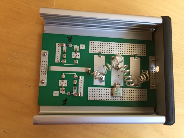
The RF board and layout is based on W6PQL design. I made the 9:1 input transformer myself from a slightly larger semi than the original design. I will use a MRFE6VP61K25H LDMOS.
The software is written in Dot.Net.
Mounting the LDMOS using Liquide Pro. I have now changed this to MX-2 made by ARCTIC, it works better. Liquide metal can cause a short if small droplets is pressed out when the LDMOS is tightend to the heat spreader.
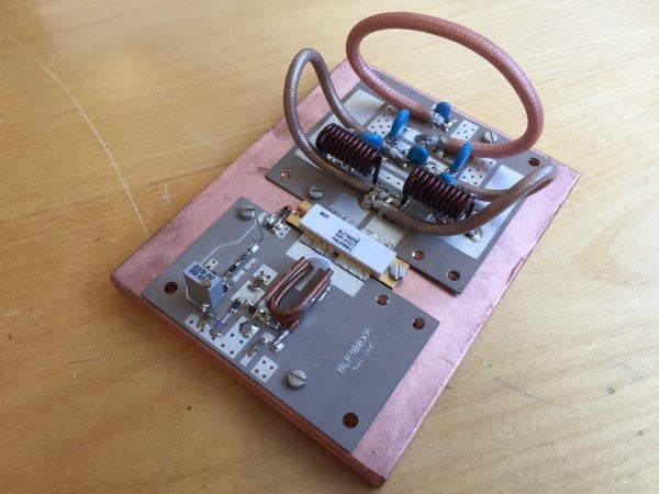
Complete pallet.
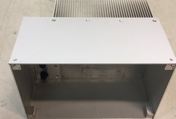
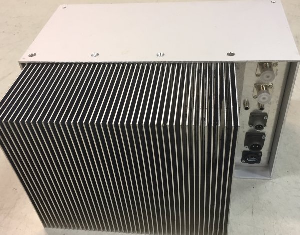
Some hardware done building the cabinet.
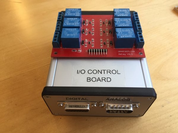
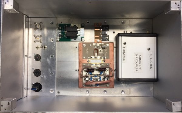
The I/O is mounted in a box to shield from RF. Analog and digital signals is controlled from the software. A 6 channels relay board is located at the top and makes a good isolation between the I/O and the other circuits.
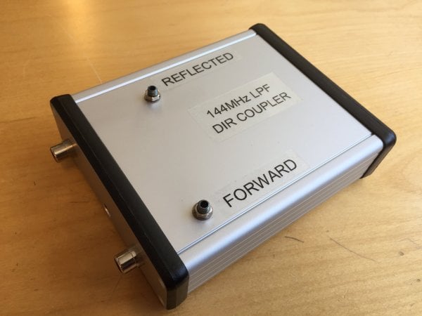
The LPF and directional coupler is also mounted in a shielded box.
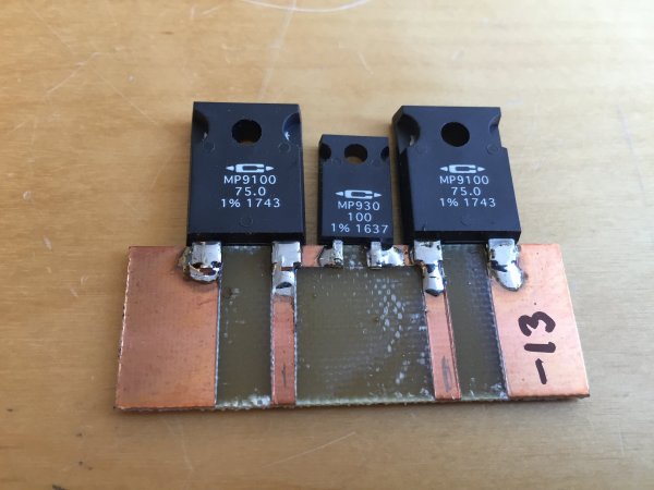
I was going to use my FT-847, which has 50W output. Therefore I made a simple attenuator of -13db. Just cut out the striplines with a razor blade knife. Now I have replaced the attenuator and I also now use my IC-9700.
Progress...
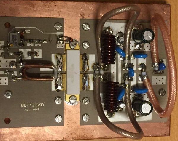
Part 2. Another Pallet.
The above pallet output stage burned up at about 700W out. For some reason it was not stable. Now I have a new one which is working great.
The new Pa is built with R3KR 144 board.
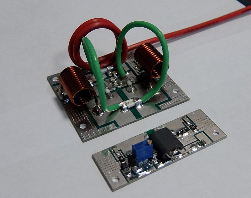
This PA can deliver > 900W. A small YouTube movie shows the PA in action.
https://www.youtube.com/watch?
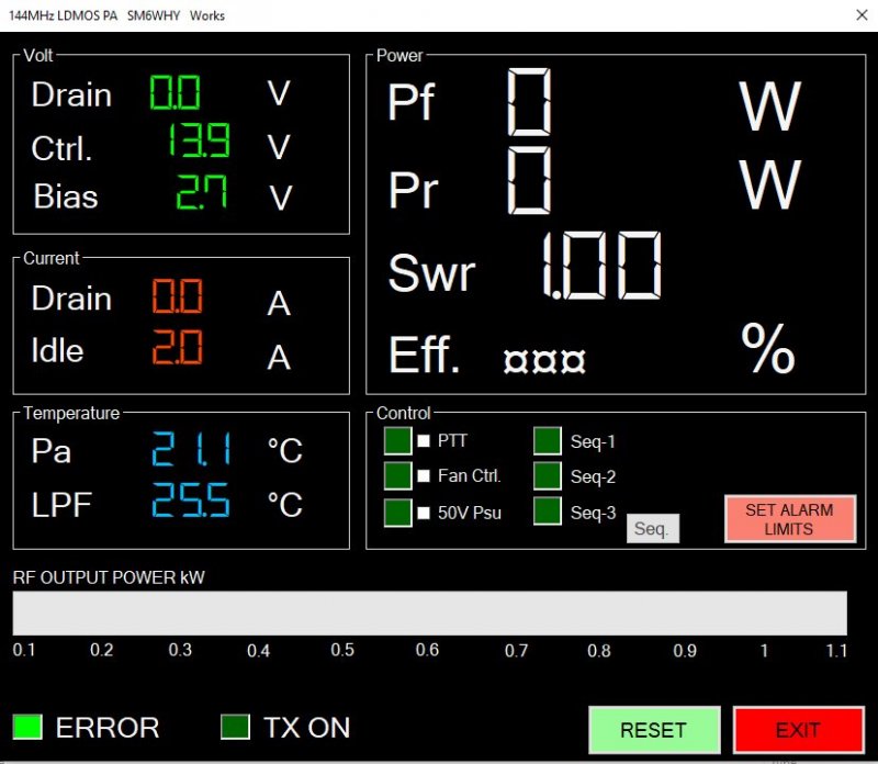
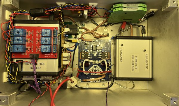
Inside PA:
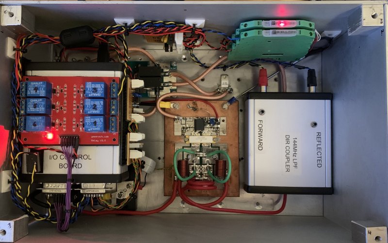
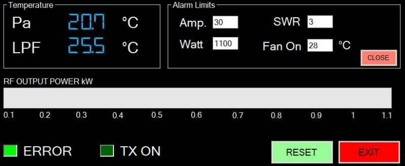
All safety is located in the software. If this is wise or not will the future answer. The reading speed for the parameters is about 50mS, so it is far from the speed of a microcontroller based system. The limits can be set as requested. If an error occur the ERROR lamp goes red and the PA goes to STBY and the RESET button must be pressed.
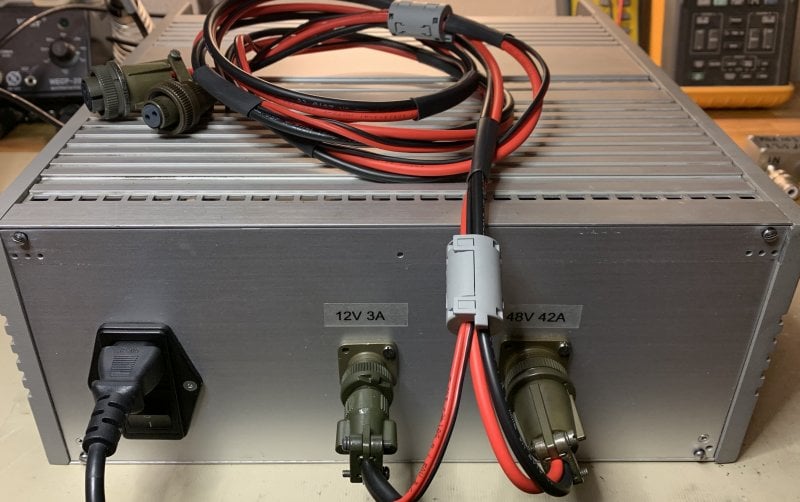
The PSU for this PA will be built using 2 rather cheap modules available on the net. My came from Germany and costed about 90 Euro. Cabinet, contacts and metering will be added. However I will use most surplus I already have. 2kW is maximum output power.
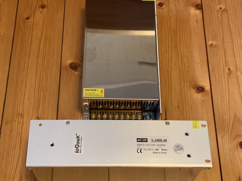
The PSU modules is 48V 21A each. To be able to work in parallel a powerful diode is mounted on each plus out. I used 2 85HF20. This prevents the PSU's from overloading and shutdown.
Live testing in a NAC contest:
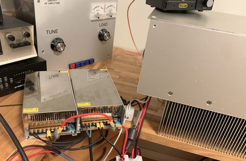
Final 2 kW PSU:
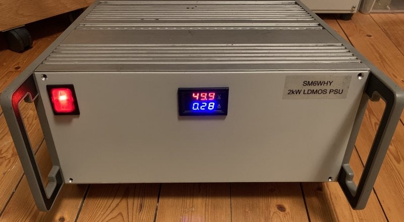
Here in action with new panel meters. 48V and 25A at +700W out. Efficiency about 60%.
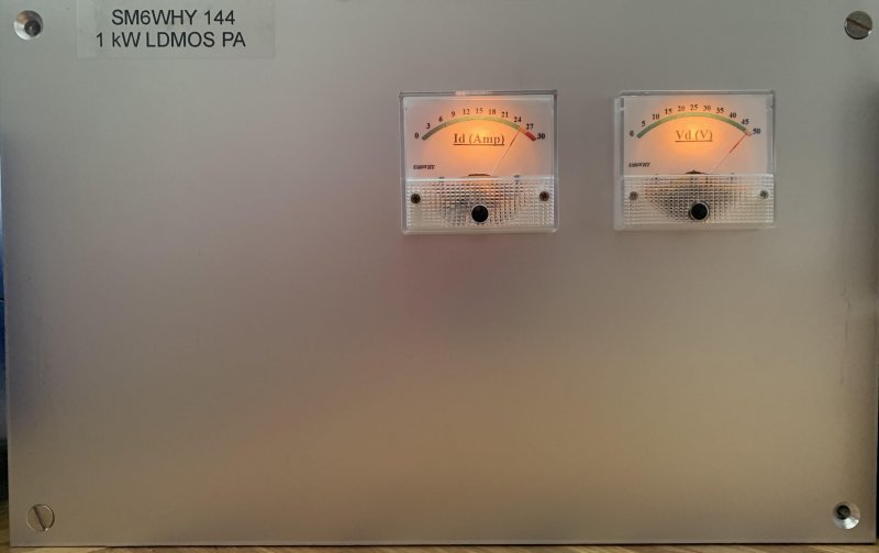
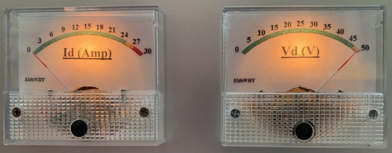
I made new meter scales using Galva.
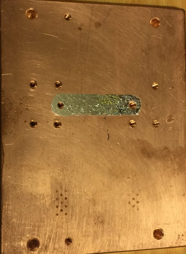
Sometimes things happens. The MRFE6VP61K25H burn up.
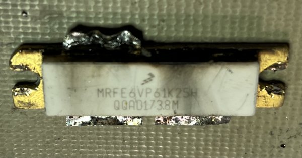
It has been a working horse for several years. It seems that during digi modes the heat killed. Probably was the mounting not perfect. The PCB was quite destroyed by the heat.
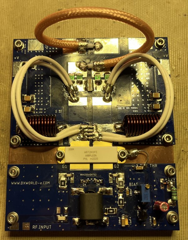
A new replacement was needed. One nice transistor is the MRF-300. DX-World has a neat PCB. I was thinking that 500W is good enough. I ordered one, installed and running.
So, installed and working. Nothing to complain about. However, the QRO devil is still sitting on my shoulder. Is 500W enough? (Probably) but....
Who cannot love this one:
Based on Advanced Rugged Technology (ART), this 2000 W LDMOS RF power transistor has been designed to cover a wide range of applications for ISM, broadcast and communications.
VDS of 65V makes my 50V a charm. 2kW output makes my modest 1kW modest.
Well, this is it. If you really want a kilo Watt safe on 144 use the ART2K0FE. It can handle twice the power and does not get very hot.
A short video in action:
Welcome
Welcome to sm6why.n.nu.

My Newsletter
Links