
Spectrum Analyzer Extender
Since I sold my HP8555A (which covers up to 18GHz) I have been blind over 23cm frequencies. My “new” analyzer is the Tektronix 2712 with inbuilt tracking generator up to 1.8GHz.
6 and 3cm are however nice to able to “see” if you are going to play with transverters, Lo, Gun diodes and doppler DROs.
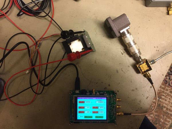
Here is my simple spectrum analyser range extender. It consists only of a frequency source and a mixer.
I have tested harmonic mixing before, but it is rather painful actually, all harmonics and mirror frequencies are seen at the display so you must know what you are looking for.
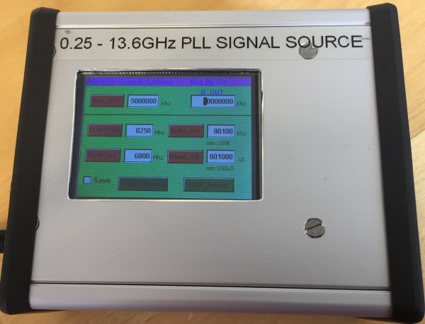
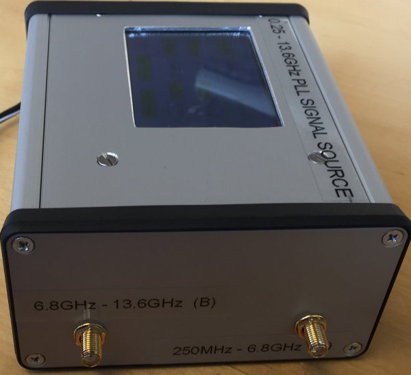
The signal source is an ADF5355 PLL with a control software. Range 250MHz to 13.6GHz.
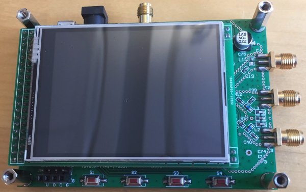
The module needed a housing I included a 5V regulator, diode and fuse protection.
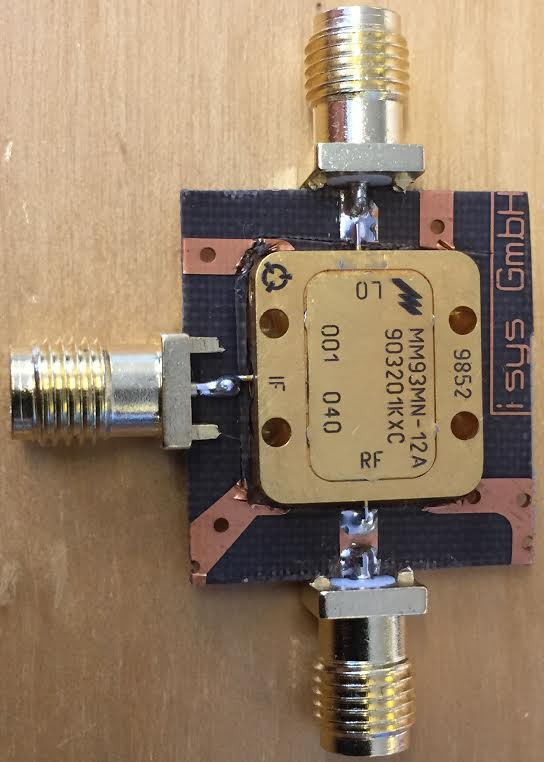
The mixer is a surplus gift from an amateur friend SM6VFZ. RF-LO 6-18 GHz, IF DC-4.5 GHz, P-LO=7dBm
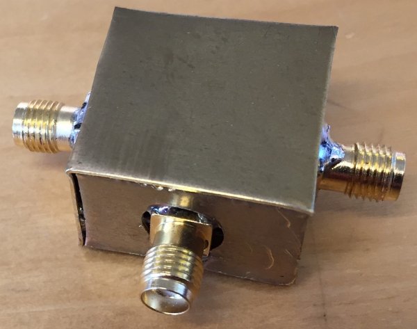
I used a piece from a surplus SU-02 board. And made a simple brass box.
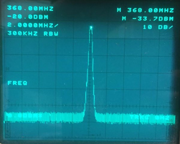
A test with a HB-100 doppler module.
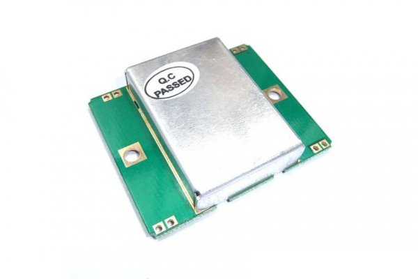
I set the LO frequenzy to 10GHz and the spectrum analyzer to 368MHz. Then I tuned the HB-100 to the center frequency.
Now my spectrum analyzer center frequency is 10.368GHz.
To be able for absolute power measurements a calibration with a known source is necessarily. However frequency and maximum gain tuning works fine.
The loss in the mixer DC-2GHz IF is typical 6db, that assumption and accuracy works fine for me.
Note:
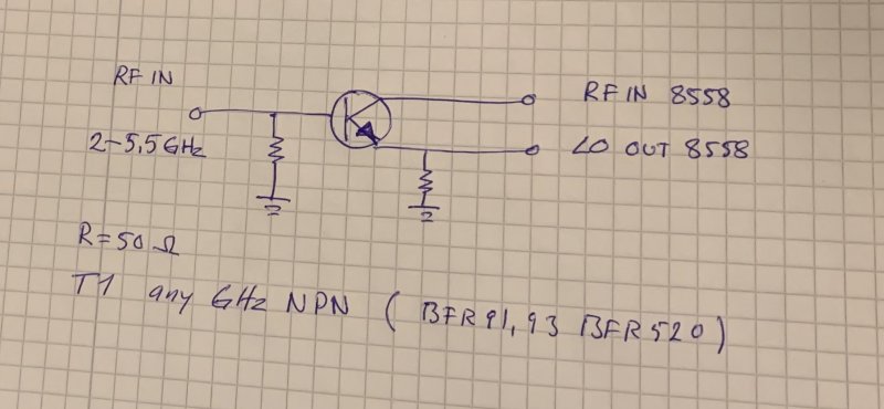
If you have a Hp-8558 SA and need to extend the range you can do this with only 1 transistor and 2 50 Ohm resistors.
The first LO out from the HP8558 is 2.055GHz this is equal to 0 MHz on the display to 3.555GHz which is 1500 MHz. Feed this first LO signal to a mixer out from the mixer goes to the inlet of the spectrum analyzer. This means that 0MHz on the display will be 2.055GHz and 1500MHz will be 5.555GHz. The "new" range will then be 2.055 to 5.555GHz.
Note: Since the range now is 3 GHz will this make a dispersion setting of 5MHz 10MHz.
Use a suitable UHF transistor Ft 7-8GHz connect the emitter to LO out collector to the 8558 RF In base and emitter goes to earth with a 50 Ohm resistor. Signal in on the base.
Welcome
Welcome to sm6why.n.nu.

My Newsletter
Links